
Download EAGLE from http://www.cadsoftusa.com/download-eagle/?language=en.
Install EAGLE
Open EAGLE
In the Control Panel menu select File>New>Project

In the dialog box, name your Project RGB_Board

In the left window of the Control Panel menu, under Projects>eagle>RGB_Board , click [RMB] and select New>Library

In the Library window, create a new device by clicking Library>Device or [Device]

In the Edit dialog window, name the device RGB_LED and click [OK]

A warning dialog will pop up saying Create new device 'RGB_LED'? click [Yes]

In the Library window, create a new Symbol by clicking Library>Symbol or [Symbol] 

In the Edit dialog window, name the device RGB_LED_SYM and click [OK]

A warning dialog will pop up saying Create new device 'RGB_LED_SYM'? click [Yes]

First you want to select the wire command. You can select Draw>Wire, click [CTRL] + [W], or click [wire] 

Draw a box using the wire comand you selected in EAG.Prj.lib.dev.sym 4.
If you make a mistake you can use the move tool
Edit>Move, click [CTRL] + [M], or click [Move]  to click and drag the corners.
You can also use the delete tool
Edit>Delete, click [CTRL] + [D], or click [Delete]  to delete an item by clicking on it.

To create sloped lines you will need to switch from the default wire bend style to [Wire Bend Style 2] by clicking the button as shown below or

Draw the diodes and then insert pins using Draw>Pin, click [ALT] + [P], or click [Pin] 
You can rotate the pin by clicking [RMB] and the green circle is where you will conect it to the rest of your symbols.
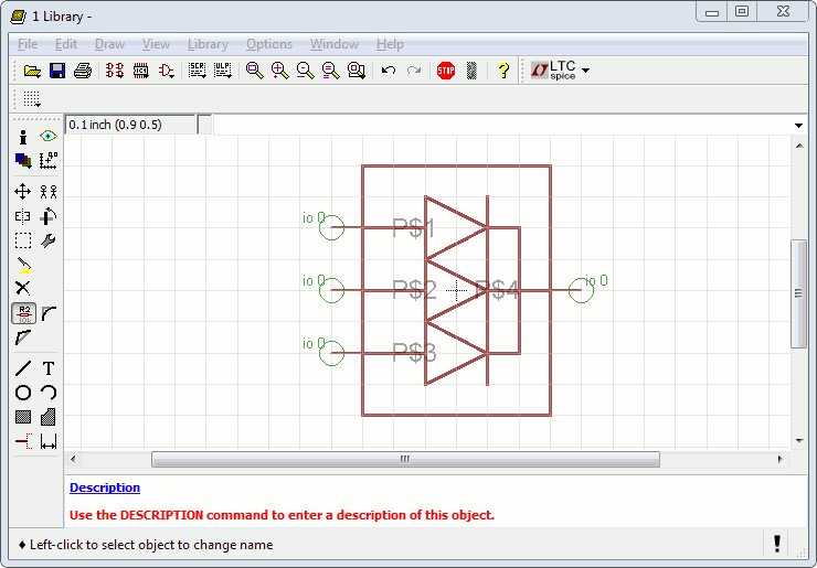
Rename the pins using
Edit>Name, click [CTRL] + [SHIFT] + [N], or click [Name] 
By clicking on the center of the green circle, the Name dialog box will pop up. Name the three pins on the left 'RED', 'GRN', and 'BLU'. Name the pin on the right 'COM'.

To make it a bit easier to read, move the sides of the box out by selecting the [move] cmd then click the group command
Edit>Group, click [CTRL] + [G], or click [Group] 
[LMB] and drag a box around what you want to move, then [CTRL] + [RMB] and drag to move the items.
 name 10
value 11
name 10
value 11
In the Library window, create a new package by clicking Library>Package or [Package] 

In the Edit dialog window, name the device RGB_LED_PKG and click [OK]

A warning dialog will pop up saying Create new device 'RGB_LED_PKG'? click [Yes]

The first thing we will do is setp the grid
View>Grid, [Grid]  .
.
'.05' '.0125'

Next open up the spec sheet.

The first thing we will do is place pads
Draw>Pad, click [CTRL] + [P], [Pad]  .
.
Each pin is placed

Now select the circle tool
Draw>Circle, [Circle]  .
.

Select the tPlace Layer

Click dead center, and then click at 0.1 in in any direction.

Select the arc tool
Draw>Arc, [Arc]  .
.

Draw an arc anywhere, then select the info tool
View>Info, click [CTRL] + [I], [Info]  .
.
and double click on the circle. Change its paramiters to blah blah
 draw a bar 12
Select the tDocu Layer see step 8

Select the Text tool
Draw>Text, click [CTRL] + [T], [Text]  .
.

Change teh text size

Name the pins R G B C
 name 17
value 18
Join components
Might just rip the rest from the PDF for now
name 17
value 18
Join components
Might just rip the rest from the PDF for now